In the software world if you want to start probing a system you have your go to tools (nmap, whois, web app scanners, etc…). They automate a lot of the grunt work and generally give you somewhere to start looking for bugs. In the hardware world you have… well you don’t really have much. Or so it may seem. Hardware for the most part is simple. Simple in the sense that there isn’t much abstraction as there is in the software world. In fact, a lot of the technologies in hardware have been in existence for decades and are still in use today.
The goal of this post is to shed some light on some of these “technologies” or hardware implementations so that you can start taking apart stuff and seeing how disparate products will usually incorporate the same design methodology. Long term (series of posts) I would like to illustrate embedded system hacking, from simple circuit bending to modifying firmware. But first we need to probe our target.
I will be walking you through a real world example of probing but first let’s set some stuff up….
Hardware Protocols in a Nutshell
Picture this, you just took apart your cable box (I don’t condone this as it can be highly illegal and expensive) and you ask “What am I looking at”? Or “Where do I start”?
Where do you start? One of the most helpful things when hacking embedded systems is getting feedback. Take for example a router you’re fuzzing or a thermostat that isn’t responding correctly. Typically these devices don’t give feedback in the traditional sense (think of your monitor as feedback when hacking software). What would be really helpful is if you can get access to a shell on it and see how the OS responds to your actions.
Side Note: I say OS think linux. Depending on the target a lot of them will run either a proprietary RTOS (real time operating system) or a variant of RTOS Linux. Why linux? Well it’s generally cheaper and it works well with a lot off the shelf hardware. Regardless, these OSes will generally have some sort of serial shell (you may see busybox associated with Linux systems, it’s just a wrapper for a set of tools).
Similar to the software world, in hardware you have communication protocols. How does a Ralink Wifi IC talk to a TI processor? Protocols had to be made and today we will use one: UART (Universal Asynchronous Receiver/Transmitter). There are a lot of different protocols you can sniff but hands down UART is the most helpful for shell access (which is what we are looking for). Here is a quick list of common protocols and how they can be used to attack a system. This list isn’t meant to be extensive or detailed. Just a quick rundown of how I have used the protocols in the past:
UART: Don’t worry about the asynchronous part. Think of this as serial access. The same way you access a Cisco router (set baud rate, 8n1). That’s what this is. Generally used for shell access (debugging) but can sometimes be used to communicate between complex systems (ex. The iPhone OS processor would communicate to the baseband via a serial line. It would send commands to it anytime you used the phone portion of the OS) since it is the probably one of the more robust protocols.
I2C or SPI: These can be more complex since they add a timing signal (in the case of SPI you can “read” on the clock rising or falling edge). Generally if you want to sniff communication between an IC or extract firmware from flash you will use these.
JTAG: Probably one of the more confusing of protocols since there is so many implementations and any manufacture can choose how they want to use it. If there is anything you need to know about JTAG is that it used for “middle logic”. So if I2C/SPI are low level stuff (think data being fetched from flash) and UART is high level (shell access), Jtag is somewhere in the middle. JTAG, depending on implementation, can give you access to the processor’s registers/regions of memory that would otherwise be blocked by the OS. Here is a scenario: you discover that the device you’re probing has a separate firmware that it never uses. You’re guessing that this could be a recovery state but you can’t seem to trick the OS into booting it. Well you could use jtag to access low level memory and modify the boot chain (the order in which things are loaded). That’s it for JTAG, don’t really worry about it now. This is just to get you a rough understanding of its uses.
OK so protocols, check (There are more plenty more and variations of them, but these are some of the most common). As part of the reconnaissance phase, you want deeper access to the device than what is typically presented in normal operations. One way we can peek under the hood is by getting access to the operating system inside. Access to a shell would be ideal. This can be exposed numerous ways. Some devices have a telnet port you can use or enable in software. In the event this isn’t an option, you can use hardware to obtain access to a shell. UART is the typically the protocol used to access this hidden shell. In order to do this you need to know where those points are on the PCB. That’s what we’re looking for, UART pins/pads. So I promised we would be looking at a real world piece of hardware but so far you just read a whole bunch of stuff about protocols and shell. Well most people think hardware hacking, they picture some guy with an oscilloscope, power supplies, wiring everywhere. In reality this stuff is helpful and it can sometimes be like that. But hardware is more about an understanding of embedded design and the fundamentals. In fact you could probe most systems with a multimeter and a $5 cable, which is what we will be using today. If you haven’t noticed by now, rather than just tell WHAT I did or WHERE I looked. I want to give insight as to WHY. Think of this as a film with commentary.
Note about hardware: A decent multimeter will do. Early on I used a craftsman brand meter for years till it broke. If you have never used a multimeter before I would highly recommended playing with it first (youtube some videos) and get comfortable using one. If not, fine. Really all we will be using is the volt meter and continuity test portion of it.
Get yourself a usb to uart bridge. The PL2303HX is a popular adapter. You can get it from amazon for $5.
Reconnaissance walkthough
Ok so finally our first target…the Belkin WeMo switch. Early this year I discovered several vulnerabilities on the wemo and will be using it to illustrate the concepts in this post and possibly subsequent posts. Here is the PoC post (via HackaDay):
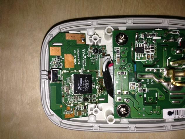
Ok so after taking it apart you’re are left looking at this.

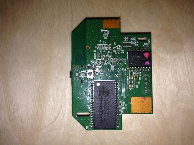
We will be focusing on the top portion as this houses the logic. For edification purposes, the bottom is mostly a relay and other circuitry to convert from mains to usable DC voltages. Here is the front and back:


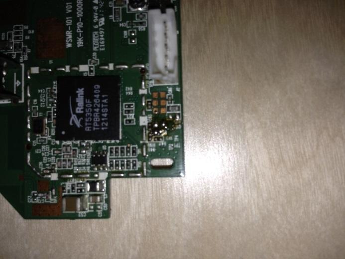
The front houses a Ralink SoC and on the back you see some RAM and flash. I plan to dedicate a post to system design if there is enough interest but for now I’ll just tell you what the ICs are.
First thing we do is look at the subject and “read” the board. On the back you see the two components and some large pads. On the front we see the processor, more large pads, a connection header, and….

(Sorry for the solder, this was a test unit. Out of the box the pads would look like the ones to the right)
Perfectly arranged pads. If you have haven’t guessed it, reading the board is looking for anomalous exposed pads/connections. Generally everything on the board is used by something else but for debugging purposes hardware designers will leave something like this to “tap into”. Sometimes it’s easier to spot because they will come with headers soldered on them (popular with routers). We have an “area of interest” and now it’s time to pull out our multimeter.
Wait wait…before we start poking at things we need to know what to look for and why. First we need to understand UART a little bit more. UART is a simple communication protocol to understand since it has close ties to legacy systems (See RS232 note below). It composed of two lines Rx/Tx (Receive and Transmit). It’s asynchronous because there is no clock signal. Instead the bitrate (sometimes called baud rate) is set depending on implementation. I won’t go into too much detail here but to probe for other protocols you will need an oscilloscope/logic analyzer since an external clock signal is used.
RS232 notes: So remember that joystick you used to plug in the back of your beige box PC? You might think of that as serial. So what is UART? Why are you confusing me? The short answer, it has to do with voltage levels and terminals. In the legacy days serial protocols were used to access machines from dummy terminals. It required higher voltages and a different way to communicate. RS232 is a specific implementation of a serial protocol. It operates on voltages of +15v to -15v. Small ICs (dense boards) can’t handle that so they used a different voltage level to convey high/low. You might hear TTL or CMOS logic levels. There are others but these are hands down the most used. It all has to do with what the end device considers high/low from a range of 0V to 3V/5V. Just make sure the device you’re using (USB to UART bridge) supports what the target is using.
Fun Fact: Voltage levels are related to heat and size. As things get smaller they require less voltage and will produce less heat. That’s how we are able to shrink things to tiny sizes. If they were using levels in the 15v range it would require more space to dissipate the heat generated. So much so, it is becoming popular (in really dense systems) to use 1.8v logic levels.
OK so UART/Serial stuff out of the way lets go back to the wemo.
Ideally UART points will come in bunches of 4 (tx, rx, power, ground). This is not always true though (they can be separated, only tx/rx are exposed, etc…). The best methodology to use is process of elimination. We are looking for a Tx/Rx signals. You will need ground for the adapter but it is so easy to find that I don’t even consider them. Ground pads are actually the first to be removed from the “candidate pool”.
First, with the device off, let’s get rid of any ground pads. Find a known ground point on the board and use the multimeter’s continuity test to see if any of the pads are tied to it. You can do this with the device off and is relatively safe.
Now for power (Vcc), with the device on (preferably at startup, since Tx and Vcc can be deceiving, you’ll see how later) set your multimeter to measure dc voltage and look for the steady operating voltage. Devices will more than likely run at 3v/5v but it isn’t always the case and you might have to look at the datasheet to be sure. The important thing is that whatever you’re measuring doesn’t change. I normally don’t bother looking for Vcc as the described test above isn’t accurate. But for the small amount of pads exposed here, I decided to eliminate any high steady signals from the candidate pool.
Now, ideally you would want use a logic analyzer and any remaining candidate pads but practically you won’t need it. Why? Experience. A lot of times UART taps will have a header with pins soldered already or possibly even labeled (J1, J2, Jx…).
With a multimeter and some tips you can increase your odds.
Tx will generally jump from low to high (bits being transmitted) so with your multimeter you can detect this. It won’t be steady like Vcc. If your meter is sensitive (make sure it isn’t averaging either) you will notice it “jitter”. This is seen better at boot (as debug information is sent out) and can “disappear” once the unit has booted. Serial can also be suppressed so it’s best to look for this “jitter” as early as possible. You can then verify it by hooking up the receive line of your USB adapter. Two things to remember….
- The Tx from the target goes to Rx on the adapter. Same goes for Rx.
Tx (target) -> Rx (adapter)
Rx (target) -> Tx (adapter)
- Make sure your operating voltages are compatible. Don’t use an adapter rated for 5v when your target is using 3v. A lot of adapters can be used for both though. See the manual it came with.
Assuming the pad is Tx, your desktop client (putty for windows or Minicom for Linux) will need some settings. Luckily 8n1 is the unofficial standard but the datasheet should confirm this for you. For the baud rate here are some tips:
- Guess. Try all available baud rates and see which one reads the signal correctly (least favorite, rarely use)
- String out the u-boot header. This requires that you have the firmware available and know how to deconstruct it (Cover in later posts). If you do, a lot of times it will have the serial settings in the text. (1st choice if I can get the fw)
- Logic Analyzer. If you have one, more than likely they will have a feature to guess the baud rate. (This is what I use but would require you to purchase an additional piece of equipment).
That’s it for Tx. Now for Rx. The receive pad is probably one of the more difficult pads to fingerprint since its just waiting for input to be sent to it. Typically, if measured with a multimeter, this pad will be pulled low or “floating”. This is where the reading a spec sheet helps. It will describe the pins schematic in more detail. Sometimes Rx has to be pulled low via a resistor to ground (which is typically the case with floating voltages). Again experience helps with this and you’ll see that a lot of time where there is Tx, Rx won’t be too far off. Same goes for hooking up the adapter in the case for Tx. It is important to get Tx working since you will need the correct baudrate in order for Rx to work. If you don’t know the baudrate (didn’t get Tx working) then you won’t know if it’s the wrong pad you have or at the wrong baudrate. Eliminate the variables, find Tx/Baudrate first. This is what you want to see:
(This isn’t the wemo but the idea is the same)
Now disclaimer…It isn’t always this easy. There are a lot of techniques to prevent shell access (serial suppression, covered pads, kernel patching, etc…) I might do a post about UART security but for now this is a start. Practice helps so I’d recommend taking something apart (recommendations below) and getting some hands on experience. If you have any questions feel free to ask or if you run into a roadblock, send me some pictures (dviciousb@gmail.com or via twitter @danielbuentell0). I’ll try to point you to the right direction.
If you made it this far here is your prize:
This is possibly one of my favorite hardware RE games (there isn’t many). It isn’t true to real world hardware but it presents the foundations in a fun way. Best of all…it’s free.
Happy Hacking,
Daniel B.
No comments:
Post a Comment